Polarization filters
Producing circular polarised light. In circular polarization the electric vector has a constant magnitude, but its direction rotates in a plane perpendicular to the direction of propagation. It is defined as right-handed if the sense of rotation is clockwise as viewed by the receiver; left-handed if anti-clockwise.
The 3-D glasses
The analysers in your glasses have a quarter wave plate in contact with a linear polarizer that is closest to your eye. The quarter wave plate will shift the relative phase by 90 degrees. The linear polariser is arranged so that the x and y components are now in phase, i.e. linearly polarised, in a direction that will pass through the linear polarisation filter. The filter for the left eye is arranged so that the opposite occurs for the left eye.
Quarter wave plate will only shift exactly at one wavelength.
Look at a light source through left and right lenses.
Also try the glasses in reverse; they will produce cpl
Try linear in front of glasses. Or look at a screen, although it is easier to rotate a linear filter.
Try linear filter between after glasses and eyes.
If you have two pair of glasses Hold one in front of the other.
Use one pair of glasses in reverse. Look at the light from the reversed right eye with both left and right. Now look at the left eye.
Try place different objects in front of the left and right analysers. Alternately closing eyes you can confirm that each eye has a different view.
2.2 The law of Malus.
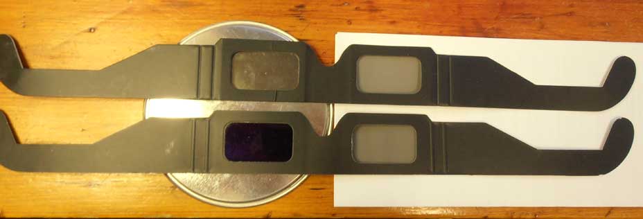
Hold two linear polarisation filters up to a randomly polarised light and change their relative orientation. When their polarisation axes are aligned they should transmit the maximum amount of light (Imax). When their axes are at ninety degrees the should transmit the minimum amount of light. (The cheap filters we are using in fact will always transmit a very small amount of light at the short wavelength end of the spectrum, hence rather than black you will usually see a deep purple.)
The intensity I the of transmitted light should follow the law of Malus, i.e.
I = Imax cosΦ
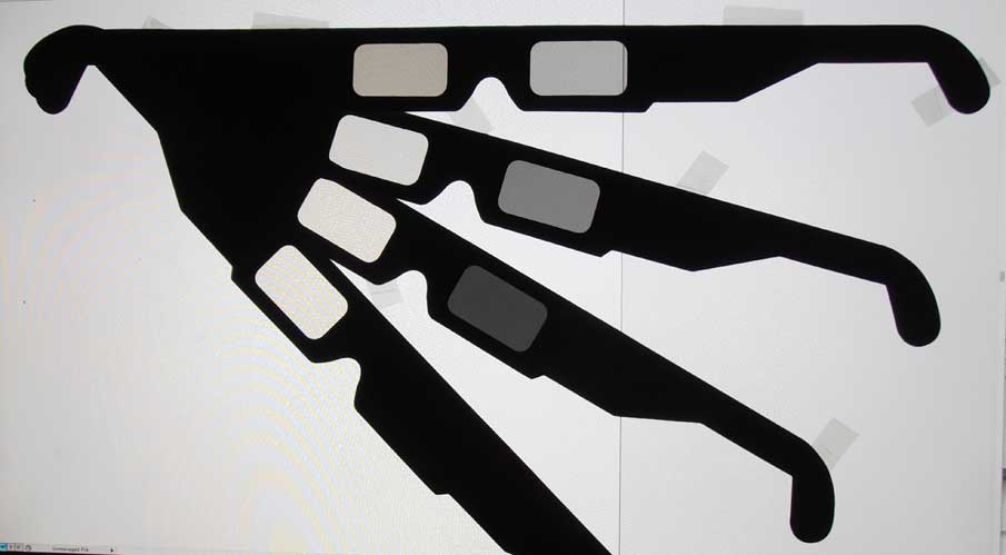
where Φ denotes the angle between the planes of polarisation. This can be tested by photographing your filters with different orientations. It is best if the aperture and exposure time of your camera can be controlled so the images are all made under the same conditions. If this is not possible (for example with a simple point and shoot camera), then you will need to have something in every image that will act as a control so you can correct for varying exposures from photo to photo.
Once the images are loaded into your computer, you can use software to determine the RGB levels in appropriate places in your image. (I used the ColorSync Utility, an integral part of the MAC OS operating system)
The photo below shows an arrangement where I use an LCD screen as a source of polarised light. Taping linear polarisation glasses onto the screen allows a number of angles to be investigated simultaneously.
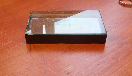
Optical birefringence
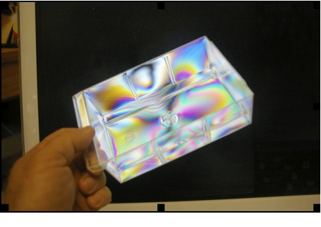
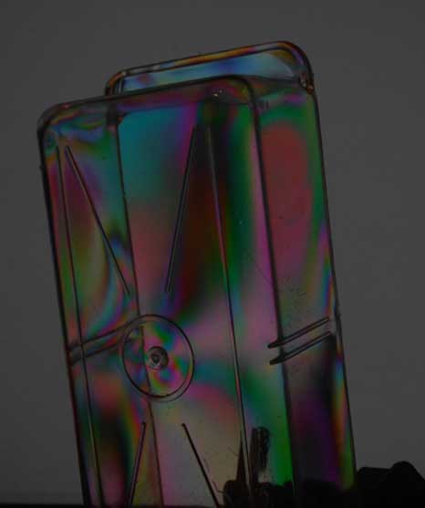
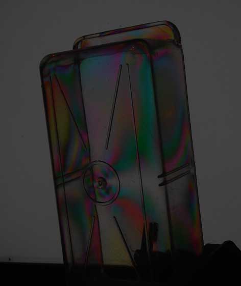
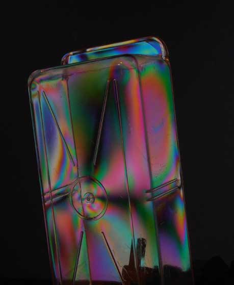
In the example shown below, an injection moulded, plastic tray is illuminated by the linearly polarized light from an LCD screen. A small piece of linear polarizing material is attached to the camera lens. The colours reveal the stress lines frozen into the plastic as it cooled. If you flex the plastic you will change the stresses in the material and change the colours .
Here are some pictures with a tray in a different orientation.
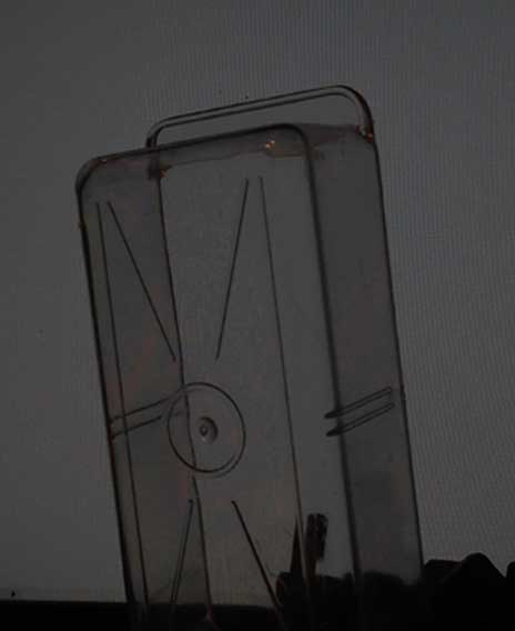
The above photo was without the filter (some faint colours can be seen where the light passed through two layers of plastic).
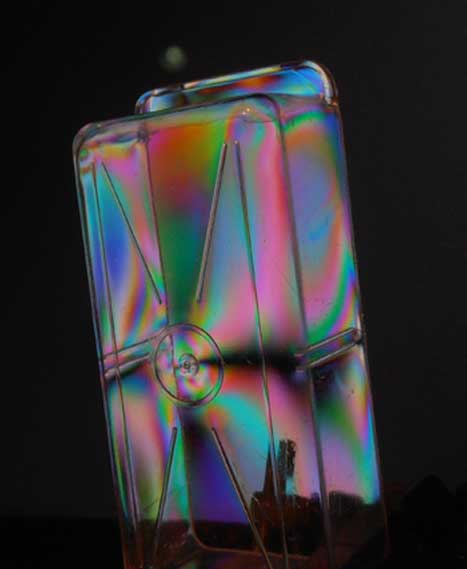 This photo was taken with the linear filter in front of the lens. This photo was taken with the linear filter in front of the lens.
|

 No filter
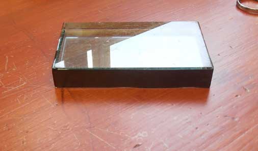 Filter passes horizontal polarization only
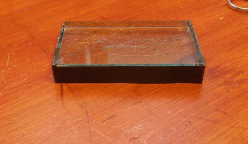 Filter passes vertical polarization only