Power and RMS values
In the last line, we have used a standard trigonometrical identity that cos(2A) = 1 - 2 sin2A. Now the sinusoidal term averages to zero over any number of complete cycles, so the integral is simple and we obtain
This last set of equations are useful because they are exactly those normally used for a resistor in DC electricity. However, one must remember that P is the average power, and V = Vm/√2 and I= Im/√2. Looking at the integral above, and dividing by R, we see that I is equal to the square root of the mean value of i2, so I is called the root-mean-square or RMS value. Similarly, V = Vm/√2 ~ 0.71*Vm is the RMS value of the voltage. When talking of AC, RMS values are so commonly used that, unless otherwise stated, you may assume that RMS values are intended*. For instance, normal domestic AC in Australia is 240 Volts AC with frequency 50 Hz. The RMS voltage is 240 volts**, so the peak value Vm= V.√2 = 340 volts. So the active wire goes from +340 volts to -340 volts and back again 50 times per second. (This is the answer to the teaser question at the top of the page: rectification of the 240 V mains can give both + 340 Vdc and -340 Vdc.) * An exception: manufacturers and sellers of HiFi equipment sometimes use peak values rather than RMS values, which makes the equipment seem more powerful than it is. ** I've written above that, in Australia (where I live), domestic power outlets have an active contact at 240 Vac. They also have a neutral contact at very close to zero Vac; this wire returns the current to the local transformer. The third contact is the earth, which is there for safety and which only carries current in event of a fault. In the US, most outlets have just two contacts: an active at 110 Vac and a neutral at very nearly zero Vac. However, some US sockets have 220 Vac potential difference between two active contacts. Both have 110 Vac, but they are 180° out of phase, so the difference between the two active contacts is 220 Vac. Power in a resistor. In a resistor R, the peak power (achieved instantaneously 100 times per second for 50 Hz AC) is Vm2/R = im2*R. As discussed above, the voltage, current and so the power pass through zero volts 100 times per second, so the average power is less than this. The average is exactly as shown above: P = Vm2/2R = V2/R. Power in inductors and capacitors. In ideal inductors and capacitors, a sinusoidal current produces voltages that are respecively 90° ahead and behind the phase of the current. So if i = Imsin wt, the voltages across the inductor and capacitor are Vmcos wt and -Vmcos wt respectively. Now the integral of cos*sin over a whole number of cycles is zero. Consequently, ideal inductors and capacitors do not, on average, take power from the circuit.
Three phase AC
|
|
||||||||
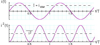 The power p converted in a resistor (ie the rate of conversion of electrical
energy to heat) is
The power p converted in a resistor (ie the rate of conversion of electrical
energy to heat) is
 Joe's scientific home page