Electric motors and generatorsElectric motors, generators, alternators and loudspeakers are explained using animations and schematics.This is a resource page from Physclips, a multi-level multimedia introduction to physics (download the animations on this page).
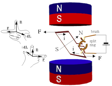
DC motorsA simple DC motor has a coil of wire that can rotate in a magnetic field. The current in the coil is supplied via two brushes that make moving contact with a split ring. The coil lies in a steady magnetic field. The forces exerted on the current-carrying wires create a torque on the coil.
Note the effect of the brushes on the split ring. When the plane of the rotating coil reaches horizontal, the brushes will break contact (not much is lost, because this is the point of zero torque anyway – the forces act inwards). The angular momentum of the coil carries it past this break point and the current then flows in the opposite direction, which reverses the magnetic dipole. So, after passing the break point, the rotor continues to turn anticlockwise and starts to align in the opposite direction. In the following text, I shall largely use the 'torque on a magnet' picture, but be aware that the use of brushes or of AC current can cause the poles of the electromagnet in question to swap position when the current changes direction. The torque generated over a cycle varies with the vertical separation of
the two forces. It therefore depends on the sine of the angle between the
axis of the coil and field. However, because of the split ring, it is always
in the same sense. The animation below shows its variation in time, and you
can stop it at any stage and check the direction by applying the right hand
rule.
Motors and generatorsNow a DC motor is also a DC generator. Have a look at the next animation. The coil, split ring, brushes and magnet are exactly the same hardware as the motor above, but the coil is being turned, which generates an emf.
If you use mechanical energy to rotate the coil (N turns, area A) at uniform angular velocity ω in the magnetic field B, it will produce a sinusoidal emf in the coil. emf (an emf or electromotive force is almost the same thing as a voltage). Let θ be the angle between B and the normal to the coil, so the magnetic flux φ is NAB.cos θ. Faraday's law gives:
= NBA sin θ (dθ/dt) = NBAω sin ωt. An alternatorIf we want AC, we don't need recification, so we don't need split rings. (This is good news, because the split rings cause sparks, ozone, radio interference and extra wear. If you want DC, it is often better to use an alternator and rectify with diodes.)In the next animation, the two brushes contact two continuous rings, so the two external terminals are always connected to the same ends of the coil. The result is the unrectified, sinusoidal emf given by NBAω sin ωt, which is shown in the next animation.
Back emfNow, as the first two animations show, DC motors and generators may be the same thing. For example, the motors of trains become generators when the train is slowing down: they convert kinetic energy into electrical energy and put power back into the grid. Recently, a few manufacturers have begun making motor cars rationally. In such cars, the electric motors used to drive the car are also used to charge the batteries when the car is stopped - it is called regenerative braking.So here is an interesting corollary. Every motor is a generator. This is true, in a sense, even when it functions as a motor. The emf that a motor generates is called the back emf. The back emf increases with the speed, because of Faraday's law. So, if the motor has no load, it turns very quickly and speeds up until the back emf, plus the voltage drop due to losses, equal the supply voltage. The back emf can be thought of as a 'regulator': it stops the motor turning infinitely quickly (thereby saving physicists some embarrassment). When the motor is loaded, then the phase of the voltage becomes closer to that of the current (it starts to look resistive) and this apparent resistance gives a voltage. So the back emf required is smaller, and the motor turns more slowly. (To add the back emf, which is inductive, to the resistive component, you need to add voltages that are out of phase. See AC circuits.) Coils usually have cores In practice, (and unlike the diagrams we have drawn), generators and DC motors often have a high permeability core inside the coil, so that large magnetic fields are produced by modest currents. This is shown at left in the figure below in which the stators (the magnets which are stat-ionary) are permanent magnets. 
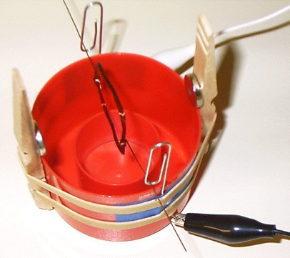
'Universal' motorsThe stator magnets, too, could be made as electromagnets, as is shown above at right. The two stators are wound in the same direction so as to give a field in the same direction and the rotor has a field which reverses twice per cycle because it is connected to brushes, which are omitted here. One advantage of having wound stators in a motor is that one can make a motor that runs on AC or DC, a so called universal motor. When you drive such a motor with AC, the current in the coil changes twice in each cycle (in addition to changes from the brushes), but the polarity of the stators changes at the same time, so these changes cancel out. (Unfortunatly, however, there are still brushes, even though I've hidden them in this sketch.) For advantages and disadvantages of permanent magnet versus wound stators, see below. Also see more on universal motors. Build a simple motorTo build this simple but strange motor, you need two fairly strong magnets (rare earth magnets about 10 mm diameter would be fine, as would larger bar magnets), some stiff copper wire (at least 50 cm), two wires with crocodile clips on either end, a six volt lantern battery, two soft drink cans, two blocks of wood, some sticky tape and a sharp nail.
Make the coil out of stiff copper wire, so it doesn't need any external support. Wind 5 to 20 turns in a circle about 20 mm in diameter, and have the two ends point radially outwards in opposite directions. These ends will be both the axle and the contacts. If the wire has lacquer or plastic insulation, strip it off at the ends.
AC motorsWith AC currents, we can reverse field directions without having to use brushes. This is good news, because we can avoid the arcing, the ozone production and the ohmic loss of energy that brushes can entail. Further, because brushes make contact between moving surfaces, they wear out.The first thing to do in an AC motor is to create a rotating field. 'Ordinary' AC from a 2 or 3 pin socket is single phase AC--it has a single sinusoidal potential difference generated between only two wires--the active and neutral. (Note that the Earth wire doesn't carry a current except in the event of electrical faults.) With single phase AC, one can produce a rotating field by generating two currents that are out of phase using for example a capacitor. In the example shown, the two currents are 90° out of phase, so the vertical component of the magnetic field is sinusoidal, while the horizontal is cosusoidal, as shown. This gives a field rotating counterclockwise. (* I've been asked to explain this: from simple AC theory, neither coils nor capacitors have the voltage in phase with the current. In a capacitor, the voltage is a maximum when the charge has finished flowing onto the capacitor, and is about to start flowing off. Thus the voltage is behind the current. In a purely inductive coil, the voltage drop is greatest when the current is changing most rapidly, which is also when the current is zero. The voltage (drop) is ahead of the current. In motor coils, the phase angle is rather less than 90¡, because electrical energy is being converted to mechanical energy.)
In this animation, the graphs show the variation in time of the currents in the vertical and horizontal coils. The plot of the field components Bx and By shows that the vector sum of these two fields is a rotating field. The main picture shows the rotating field. It also shows the polarity of the magnets: as above, blue represents a North pole and red a South pole. If we put a permanent magnet in this area of rotating field, or if we put in a coil whose current always runs in the same direction, then this becomes a synchronous motor. Under a wide range of conditions, the motor will turn at the speed of the magnetic field. If we have a lot of stators, instead of just the two pairs shown here, then we could consider it as a stepper motor: each pulse moves the rotor on to the next pair of actuated poles. Please remember my warning about the idealised geometry: real stepper motors have dozens of poles and quite complicated geometries!
Induction motorsNow, since we have a time varying magnetic field, we can use the induced emf in a coil – or even just the eddy currents in a conductor – to make the rotor a magnet. That's right, once you have a rotating magnetic field, you can just put in a conductor and it turns. This gives several of the advantages of induction motors: no brushes or commutator means easier manufacture, no wear, no sparks, no ozone production and none of the energy loss associated with them. (For photos of real induction motors and more details, see Induction motors.)Shockwave Flash (SWF) is no longer supported and you are advised not to use it. However, if you want to try these animations using SWF, try Flash version The missing animation at right represents a squirrel cage motor. The squirrel cage has (in this simplified geometry, anyhow!) two circular conductors joined by several straight bars. Any two bars and the arcs that join them form a coil – as indicated by the blue dashes in the animation. (Only two of the many possible circuits have been shown, for simplicity.) This schematic suggests why they might be called squirrel cage motors. The reality is different: for photos and more details, see Induction motors. The problem with the induction and squirrel cage motors shown in this animation is that capacitors of high value and high voltage rating are expensive. One solution is the 'shaded pole' motor, but its rotating field has some directions where the torque is small, and it has a tendency to run backwards under some conditions. The neatest way to avoid this is to use multiple phase motors. Three phase AC induction motorsSingle phase is used in domestic applications for low power applications but it has some drawbacks. One is that it turns off 100 times per second (you don't notice that the fluorescent lights flicker at this speed because your eyes are too slow: even 25 pictures per second on the TV is fast enough to give the illusion of continuous motion.) The second is that it makes it awkward to produce rotating magnetic fields. For this reason, some high power (several kW) domestic devices may require three phase installation. Industrial applications use three phase extensively, and the three phase induction motor is a standard workhorse for high power applications. The three wires (not counting earth) carry three possible potential differences which are out of phase with each other by 120°, as shown in the animation below. Thus three stators give a smoothly rotating field. (See this link for more about three phase supply.)
If one puts a permanent magnet in such a set of stators, it becomes a synchronous three phase motor. The animation shows a squirrel cage, in which for simplicity only one of the many induced current loops is shown. With no mechanical load, it is turning virtually in phase with the rotating field. The rotor need not be a squirrel cage: in fact any conductor that will carry eddy currents will rotate, tending to follow the rotating field. This arrangement can give an induction motor capable of high efficiency, high power and high torques over a range of rotation rates. Linear motorsA set of coils can be used to create a magnetic field that translates, rather than rotates. The pair of coils in the animation below are pulsed on, from left to right, so the region of magnetic field moves from left to right. A permanent or electromagnet will tend to follow the field. So would a simple slab of conducting material, because the eddy currents induced in it (not shown) comprise an electromagnet. Alternatively, we could say that, from Faraday's law, an emf in the metal slab is always induced so as to oppose any change in magnetic flux, and the forces on the currents driven by this emf keep the flux in the slab nearly constant. (Eddy currents not shown in this animation.)
Alternatively, we could have sets of powered coils in the moving part, and induce eddy currents in the rail. Either case gives us a linear motor, which would be useful for say maglev trains. (In the animation, the geometry is, as usual on this site, highly idealised, and only one eddy current is shown.)
Some notes about AC and DC motors for high power applications
Single phase induction motors have problems for applications combining high power and flexible load conditions. The problem lies in producing the rotating field. A capacitor could be used to put the current in one set of coils ahead, but high value, high voltage capacitors are expensive. Shaded poles are used instead, but the torque is small at some angles. If one cannot produce a smoothly rotating field, and if the load 'slips' well behind the field, then the torque falls or even reverses. Power tools and some appliances use brushed AC motors. Brushes introduce losses (plus arcing and ozone production). The stator polarities are reversed 100 times a second. Even if the core material is chosen to minimise hysteresis losses ('iron losses'), this contributes to inefficiency, and to the possibility of overheating. These motors may be called 'universal' motors because they can operate on DC. This solution is cheap, but crude and inefficient. For relatively low power applications like power tools, the inefficiency is usually not economically important. If only single phase AC is available, one may rectify the AC and use a DC motor. High current rectifiers used to be expensive, but are becoming less expensive and more widely used. If you are confident you understand the principles, it's time to go to How real electric motors work by John Storey. Or else continue here to find out about loudspeakers and transformers.
LoudspeakersA loudspeaker is a linear motor with a small range. It has a single moving coil that is permanently but flexibly wired to the voltage source, so there are no brushes.
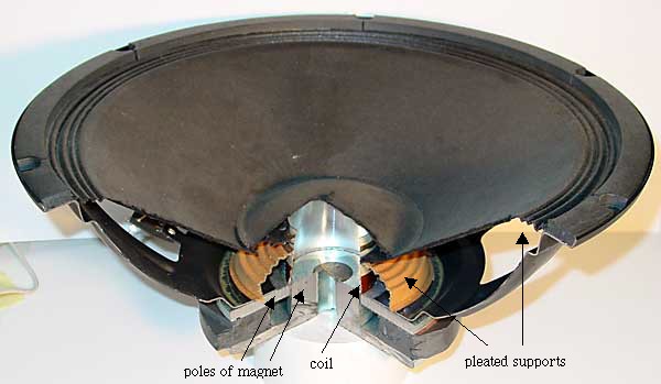
Loudspeakers as microphonesIn the picture above, you can see that a cardboard diaphragm (the loudspeaker cone) is connected to a coil of wire in a magnetic field. If a soundwave moves the diaphragm, the coil will move in the field, generating a voltage. This is the principle of a dynamic microphone – though in most microphones, the diaphragm is rather smaller than the cone of a loudspeaker. So, a loudspeaker should work as a microphone. This is a nice project: all you need is a loudspeaker and two wires to connect it to the input of an oscilloscope or the microphone input of your computer. Two questions: what do you think the mass of the cone and coil will do to the frequency response? What about the wavelength of sounds your use?
TransformersThe photograph shows a transformer designed for demonstration purposes: the primary and secondary coils are clearly separated, and may be removed and replaced by lifting the top section of the core. For our purposes, note that the coil on the left has fewer coils than that at right (the insets show close-ups).
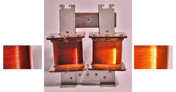
The core (shaded) has high magnetic permeability, ie a material that forms a magnetic field much more easily than free space does, due to the orientation of atomic dipoles. (In the photograph, the core is laminated soft iron.) The result is that the field is concentrated inside the core, and almost no field lines leave the core. If follows that the magnetic fluxes φ through the primary and secondary are approximately equal, as shown. From Faraday's law, the emf in each turn, whether in the primary or secondary coil, is −dφ/dt. If we neglect resistance and other losses in the transformer, the terminal voltage equals the emf. For the Np turns of the primary, this gives
VpIp = VsIs, whence Is/Ip = Np/Ns = 1/r. In some cases, decreasing the current is the aim of the exercise. In power transmission lines, for example, the power lost in heating the wires due to their non-zero resistance is proportional to the square of the current. So it saves a lot of energy to transmit the electrical power from power station to city at very high voltages so that the currents are only modest. Finally, and again assuming that the transformer is ideal, let's ask what the resistor in the secondary circuit 'looks like' to the primary circuit. In the primary circuit:
Vp/Ip = Vs/r2Is = R/r2.
Efficiency of transformersIn practice, real transformers are less than 100% efficient.
More about transformers: AC vs DC generatorsTransformers only work on AC, which is one of the great advantages of AC. Transformers allow 240V to be stepped down to convenient levels for digital electronics (only a few volts) or for other low power applications (typically 12V). Transformers step the voltage up for transmission, as mentioned above, and down for safe distribution. Without transformers, the waste of electric power in distribution networks, already high, would be enormous. It is possible to convert voltages in DC, but more complicated than with AC. Further, such conversions are often inefficient and/or expensive. AC has the further advantage that it can be used on AC motors, which are usually preferable to DC motors for high power applications.Other resources from us
Some external links to web resources on motors and generators
What is the difference between having permanent magnets and having electromagnets in a DC motor? Does it make it more efficient or more powerful? Or just cheaper? When I received this question on the High School Physics bulletin board, I sent it to John Storey who, as well as being a distinguished astronomer, is a builder of electric cars. Here's his answer: In general, for a small motor it is much cheaper to use permanent magnets. Permanent magnet materials are continuing to improve and have become so inexpensive that even the government will on occasion send you pointless fridge magnets through the post. Permanent magnets are also more efficient, because no power is wasted generating the magnetic field. So why would one ever use a wound-field DC motor? Here's a few reasons:
Opinions expressed in these notes are mine and do not necessarily reflect the policy of the University of New South Wales or of the School of Physics. The animations were made by George Hatsidimitris. Joe Wolfe / J.Wolfe@unsw.edu.au/ 61-2-9385 4954 (UT + 10, +11 Oct-Mar) |
|
||||||||
 The
coil moves in the field of a permanent magnet, which is usually shaped
to produce maximum force on the coil. The moving coil has no core, so
its mass is small and it may be accelerated quickly, allowing for high
frequency motion. In a loudspeaker, the coil is attached to a light weight
paper cone, which is supported at the inner and outer edges by circular,
pleated paper 'springs'. In the photograph below, the speaker is beyond
the normal upward limit of its travel, so the coil is visible above the
magnet poles.
The
coil moves in the field of a permanent magnet, which is usually shaped
to produce maximum force on the coil. The moving coil has no core, so
its mass is small and it may be accelerated quickly, allowing for high
frequency motion. In a loudspeaker, the coil is attached to a light weight
paper cone, which is supported at the inner and outer edges by circular,
pleated paper 'springs'. In the photograph below, the speaker is beyond
the normal upward limit of its travel, so the coil is visible above the
magnet poles.