| To begin,
let's look at a circuit that has only a capacitor and an inductor. We shall
pretend that these components are ideal, ie that they have no internal
resistance. In practice this is not possible: there will always be some way in
which electrical energy can be converted to heat, even if the rate is very
small. We begin by charging the capacitor C with an initial charge
qo. (In the demonstration shown in the photograph above, we did this
by connecting the capacitor to a battery, then disconnecting it.) We then
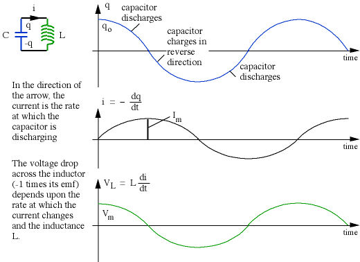
connect the capacitor to an inductance L, as shown below, and analyse the
current i that flows and the voltage V across the components.
We can substitute this solution back into the differential equation to check
that it works. Now let's look at that solution.

Provided that the components are ideal, as assumed, the charge flows back and
forwards for ever, with angular frequency wo, or with cyclic frequency f = w/2p. The energy comes from the fact
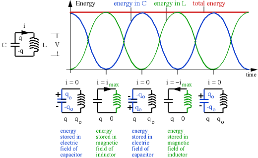
that we initially charged the capacitor with an energy
(1/2)qo2/C, which gives it a potential difference V =
qo/C. This potential difference initially drives the charge off the
capacitor. The obvious question is why the system doesn't cease changing when
the capacitor is discharged. The answer is that by this time there is a current
flowing through the inductor, and one cannot rapidly change the current in an
inductor because that would produce a large emf. In fact the energy at this
stage is stored in the magnetic field of the inductor, whose potential energy is
(1/2)L.im2. The current and the voltage for both
components are out of phase by 90° (see AC circuits), and so the
energy is transformed from electrical to magnetic and back again, as shown
below.

One can make an analogy with the simple harmonic motion of a pendulum, whose
energy is transformed from gravitational potential energy to kinetic energy and
back again. In the case of the LC circuit, the potential energy in the inductor
could be considered analogous to kinetic energy, because it depends upon the
current, ie the motion of the charge. When that charge starts to "pile up" on
the capacitor, it produces the electrical potential energy (cf gravitational
potential energy) which tends to force it back. Eventually it reaches maximum
charge (cf maximum height) and starts to discharge, with the current increasing
in the opposite direction. This is only an analogy: the momentum of the
electrons themselves is negligible, and it is the magnetic field in the inductor
that keeps them moving.
The algebra refers to ideal components, which are hard to find in practice.
Inductors almost always have internal resistance. Consequently some electrical
energy is lost as heat in this or other resistances, and there is also some loss
due to electromagnetic radiation. Each cycle loses a little energy, so the
oscillations in practice fall gradually to zero, as shown in the photograph at
the top of this page.
Now go back to the resonance section of AC circuits.
|


